The shift register 74HC595 is an integrated circuit (IC), which makes it possible to expand the output channels of the Arduino board almost arbitrarily.
Functionality
Basically, the 74HC595 shift register converts serial data to parallel data. This means that e.g. the sequence on-on-off-on-on-on-off-on (11011101) is sent to the shift register, which sends this data to its own output pins (from 1 to 8). So it turns on its Pin1, Pin2 also, Pin 3 off … and so on. These pins remain in their state until new information arrives via the data in pin of the shift register.
The shift register receives the data sent serially via the DS pin. So that it can distinguish the individual data, a kind of heartbeat is sent simultaneously via the Shift Register Clock Pin (SHCP). Finally, the 74HC595 needs a reset connection to the Arduino board. This means that three digital outputs from the Arduino are used.
Interestingly, several shift registers can be connected in series. This increases the number of possible outputs without the Arduino pins used becoming more.
By the way, you can find more information in the data sheet.
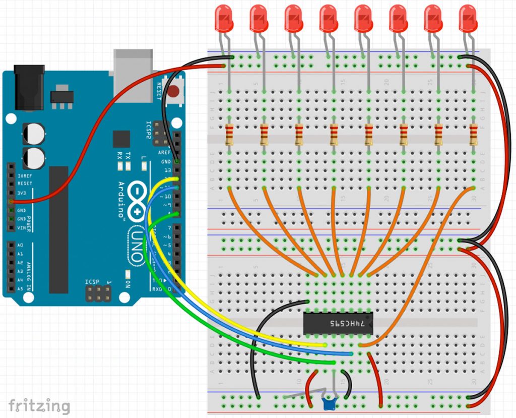
Circuit
At first glance, the circuit diagram looks a bit complex. Basically, however, only the three mentioned digital outputs from the Arduino board are connected to the shift register 74HC595. In addition, the chip is connected to GND and 5V +.
Important! The clock pin of the shift register (SHCP) must be connected to the GND via a 100nF ceramic capacitor (imprint 104)!
The individual outputs Q0 – Q7 are connected to LEDs with series resistors.
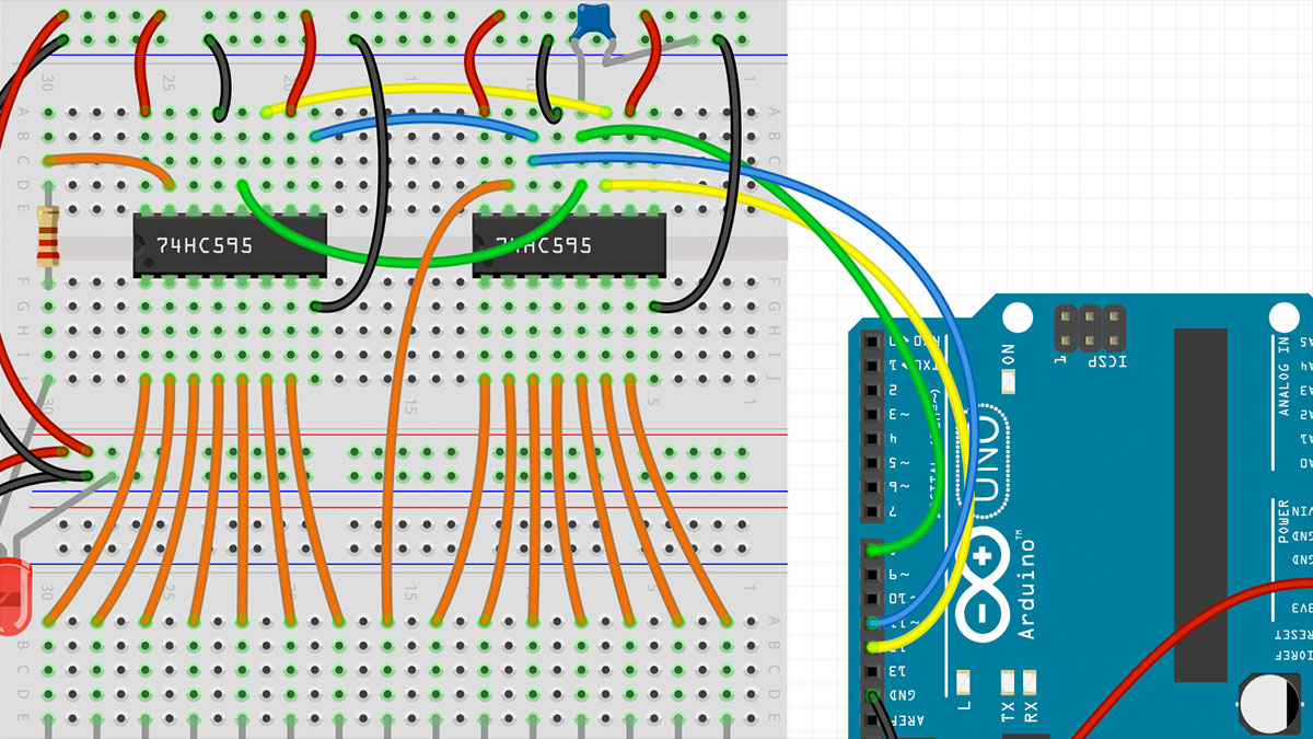
Here is the circuit diagram for several shift registers:
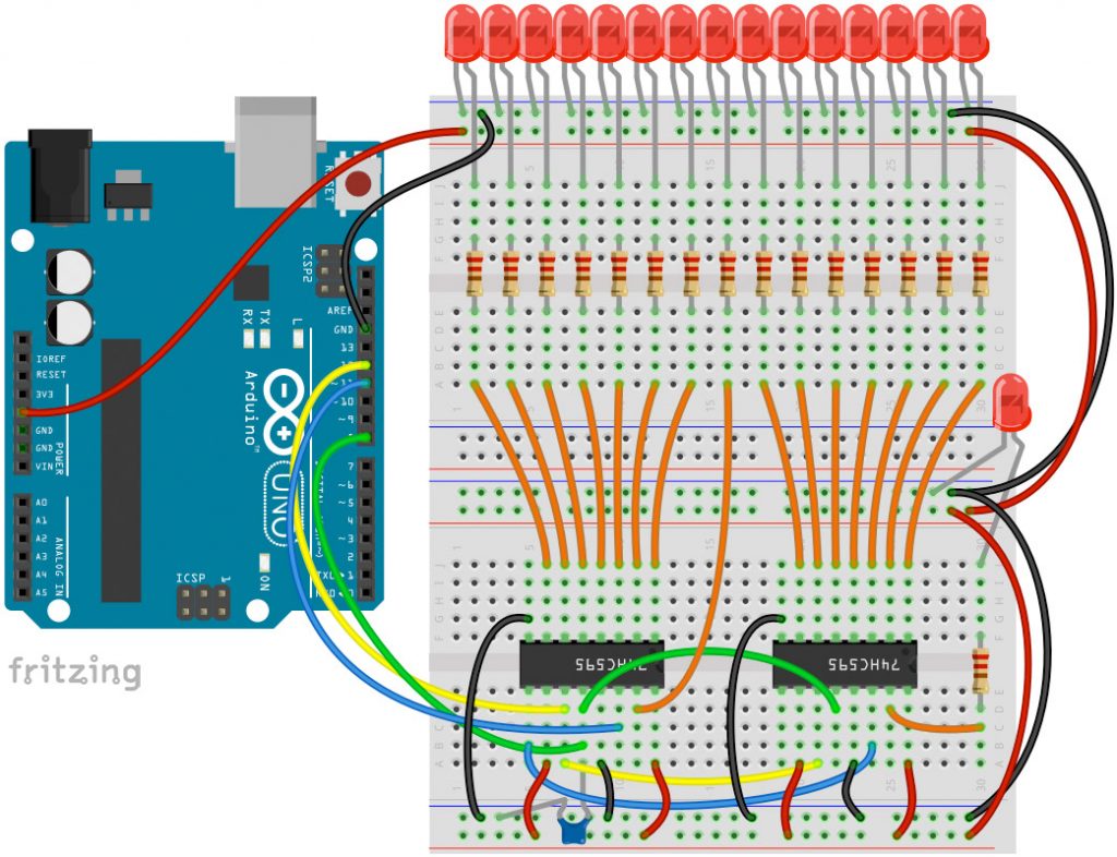
All circuits here are created with the Fritzing software.
Code for the Shift Register 74HC595
Here is the code for a single shift register:
//  Name    : shiftOutCode, Hello World
//  Author  : Carlyn Maw,Tom Igoe, David A. Mellis
//  Date    : 25 Oct, 2006
//  Modified: 23 Mar 2010
//  Version : 2.0
//  Notes   : Code for using a 74HC595 Shift Register           //
//          : to count from 0 to 255

//Pin connected to ST_CP of 74HC595
int latchPin = 8;
//Pin connected to SH_CP of 74HC595
int clockPin = 12;
////Pin connected to DS of 74HC595
int dataPin = 11;
void setup() {
  //set pins to output so you can control the shift register
  pinMode(latchPin, OUTPUT);
  pinMode(clockPin, OUTPUT);
  pinMode(dataPin, OUTPUT);
}
void loop() {
  // count from 0 to 255 and display the number
  // on the LEDs
  for (int numberToDisplay = 0; numberToDisplay < 256; numberToDisplay++) {
    // take the latchPin low so
    // the LEDs don't change while you're sending in bits:
    digitalWrite(latchPin, LOW);
    // shift out the bits:
    shiftOut(dataPin, clockPin, MSBFIRST, numberToDisplay);
    //take the latch pin high so the LEDs will light up:
    digitalWrite(latchPin, HIGH);
    // pause before next value:
    delay(500);
  }
}
Here is the code for two shift registers:
//  Name    : shiftOutCode, Hello World
//  Author  : Carlyn Maw,Tom Igoe, David A. Mellis
//  Date    : 25 Oct, 2006
//  Modified: 23 Mar 2010
//  Version : 2.0
//  Notes   : Code for using two 74HC595 Shift Register
//          : first count up from 0 to 255
//          : second count down from 255 to 0

//Pin connected to ST_CP of 74HC595
int latchPin = 8;
//Pin connected to SH_CP of 74HC595
int clockPin = 12;
////Pin connected to DS of 74HC595
int dataPin = 11;
void setup() {
  //set pins to output so you can control the shift register
  pinMode(latchPin, OUTPUT);
  pinMode(clockPin, OUTPUT);
  pinMode(dataPin, OUTPUT);
}
void loop() {
  // count from 0 to 255 and display the number
  // on the LEDs
  for (int numberToDisplay = 0; numberToDisplay < 256; numberToDisplay++) {
    // take the latchPin low so
    // the LEDs don't change while you're sending in bits:
    digitalWrite(latchPin, LOW);
    // shift out the bits:
    shiftOut(dataPin, clockPin, MSBFIRST, numberToDisplay);
    shiftOut(dataPin, clockPin, MSBFIRST, 255-numberToDisplay);
    //take the latch pin high so the LEDs will light up:
    digitalWrite(latchPin, HIGH);
    // pause before next value:
    delay(500);
  }
}
Additional Information
According to the data sheet, the 74HC595 shift register can only provide 25 – 35 mA of continuous current per channel. The STP16C596 offers an interesting and much more powerful alternative. This shift register holds 16 channels, each of which provides a continuous current of up to 120 mA. The data sheet can be found here.
Hello Sir,
Thanks a lot for the Tutorial. It helped me understand something about shift registers.
I need your help on the following:
– How can this code be modified to turn on the LEDs one by one with a command?. E.g I want to use a push button to turn on LED1, use another push button to turn on LED5 and another push button to turn on LED7
Thanks for your help.
Yeah, the question I was thinking about, have you got the solution? If you have found a solution, please share.
Error! The Arduino pin 11 should only connect to pin 14 of the first IC, not the second.
Hi Vladimir, thank you very much! You are absolutely right. I hope it’s fixed, now 🙂