Controlling with Arduino Matrix Displays is pretty easy if you make it easy! Here is my recommendation on how to do it.
Depending on the design, a matrix display consists of e.g. 8 × 8 pixels. So there are a total of 64 LEDs. Controlling them with Arduino should be quite difficult with the limited I / O pins. Fortunately, there are controller modules (ICs) that make life easier. A great series of this controller ICs is the MAX72XX line containing chips like the MAX7219.
Additional info: XX stands for all possible number combinations such as MAX7218, MAX7219, MAX721 or MAX7228. To go deeper into the matter, you can take a look at the data sheet. This is not necessary for these instructions.
I strongly recommend buying a matrix display with the MAX7219 already integrated. This saves you a lot of work, a lot of cable clutter and sleepless nights.
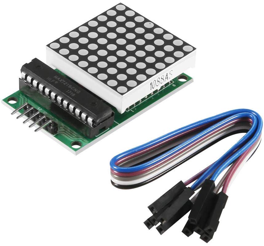
I got these:MAX7219 Dot Matrix Display Module Single-Chip Control LED Module DIY Kit for Arduino with 5pin Line* That’s two matrix displays for around ten bucks. I think that’s a good price.
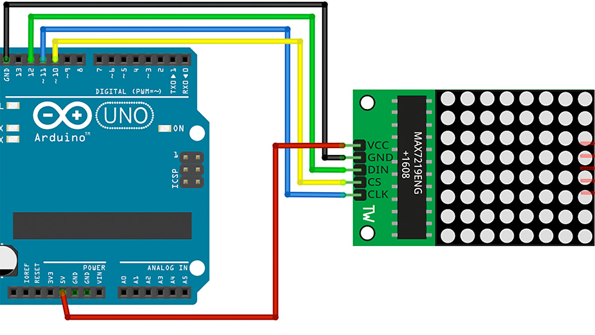
Circuit
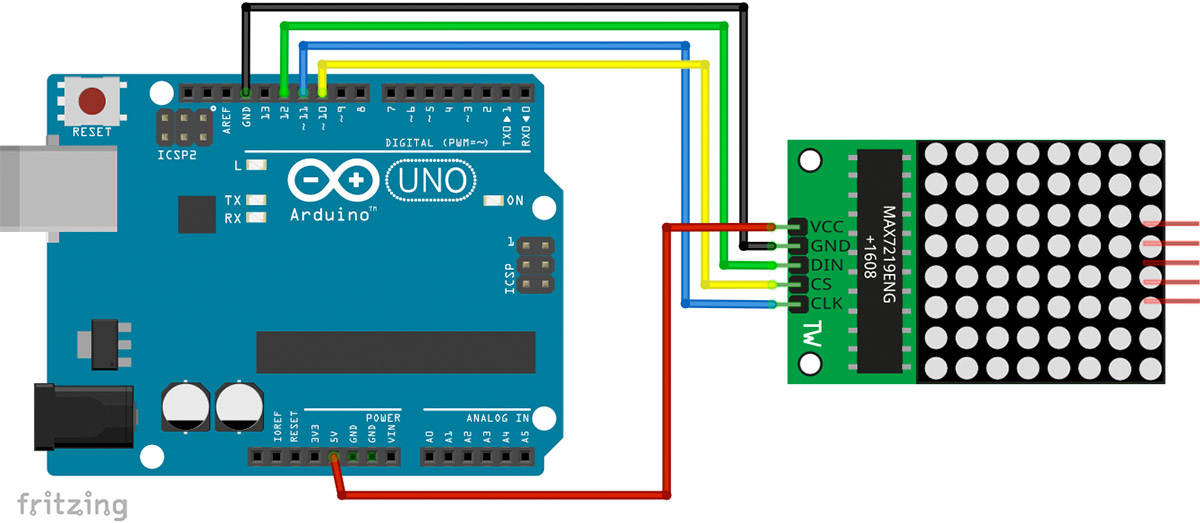
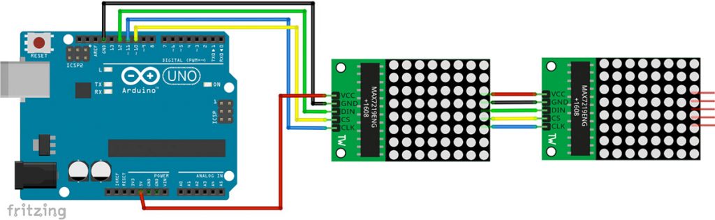
The circuit is very simple. The display gets power through the GND and 5V +. In addition, three data lines are required. The option of switching several displays in series is super useful.
Arduino Matrix Display Code
To control the Max7219, the LEDControl library has to be installed. Click Sketch>Libraries>Manage libraries and search for LEDControl. Install the current version of the library.
//We always have to include the library
#include "LedControl.h"

/*
 Now we need a LedControl to work with.
 ***** These pin numbers will probably not work with your hardware *****
 pin 12 is connected to the DataIn
 pin 11 is connected to the CLK
 pin 10 is connected to LOAD
 We have only a single MAX72XX.
 */
LedControl lc=LedControl(12,11,10,1);

/* we always wait a bit between updates of the display */
unsigned long delaytime=100;

void setup() {
  /*
   The MAX72XX is in power-saving mode on startup,
   we have to do a wakeup call
   */
  lc.shutdown(0,false);
  /* Set the brightness to a medium values */
  lc.setIntensity(0,8);
  /* and clear the display */
  lc.clearDisplay(0);
}

/*
 This method will display the characters for the
 word "Arduino" one after the other on the matrix.
 (you need at least 5x7 leds to see the whole chars)
 */
void writeArduinoOnMatrix() {
  /* here is the data for the characters */
  byte a[5]={B01111110,B10001000,B10001000,B10001000,B01111110};
  byte r[5]={B00111110,B00010000,B00100000,B00100000,B00010000};
  byte d[5]={B00011100,B00100010,B00100010,B00010010,B11111110};
  byte u[5]={B00111100,B00000010,B00000010,B00000100,B00111110};
  byte i[5]={B00000000,B00100010,B10111110,B00000010,B00000000};
  byte n[5]={B00111110,B00010000,B00100000,B00100000,B00011110};
  byte o[5]={B00011100,B00100010,B00100010,B00100010,B00011100};

  /* now display them one by one with a small delay */
  lc.setRow(0,0,a[0]);
  lc.setRow(0,1,a[1]);
  lc.setRow(0,2,a[2]);
  lc.setRow(0,3,a[3]);
  lc.setRow(0,4,a[4]);
  delay(delaytime);
  lc.setRow(0,0,r[0]);
  lc.setRow(0,1,r[1]);
  lc.setRow(0,2,r[2]);
  lc.setRow(0,3,r[3]);
  lc.setRow(0,4,r[4]);
  delay(delaytime);
  lc.setRow(0,0,d[0]);
  lc.setRow(0,1,d[1]);
  lc.setRow(0,2,d[2]);
  lc.setRow(0,3,d[3]);
  lc.setRow(0,4,d[4]);
  delay(delaytime);
  lc.setRow(0,0,u[0]);
  lc.setRow(0,1,u[1]);
  lc.setRow(0,2,u[2]);
  lc.setRow(0,3,u[3]);
  lc.setRow(0,4,u[4]);
  delay(delaytime);
  lc.setRow(0,0,i[0]);
  lc.setRow(0,1,i[1]);
  lc.setRow(0,2,i[2]);
  lc.setRow(0,3,i[3]);
  lc.setRow(0,4,i[4]);
  delay(delaytime);
  lc.setRow(0,0,n[0]);
  lc.setRow(0,1,n[1]);
  lc.setRow(0,2,n[2]);
  lc.setRow(0,3,n[3]);
  lc.setRow(0,4,n[4]);
  delay(delaytime);
  lc.setRow(0,0,o[0]);
  lc.setRow(0,1,o[1]);
  lc.setRow(0,2,o[2]);
  lc.setRow(0,3,o[3]);
  lc.setRow(0,4,o[4]);
  delay(delaytime);
  lc.setRow(0,0,0);
  lc.setRow(0,1,0);
  lc.setRow(0,2,0);
  lc.setRow(0,3,0);
  lc.setRow(0,4,0);
  delay(delaytime);
}

/*
  This function lights up a some Leds in a row.
 The pattern will be repeated on every row.
 The pattern will blink along with the row-number.
 row number 4 (index==3) will blink 4 times etc.
 */
void rows() {
  for(int row=0;row<8;row++) {
    delay(delaytime);
    lc.setRow(0,row,B10100000);
    delay(delaytime);
    lc.setRow(0,row,(byte)0);
    for(int i=0;i<row;i++) {
      delay(delaytime);
      lc.setRow(0,row,B10100000);
      delay(delaytime);
      lc.setRow(0,row,(byte)0);
    }
  }
}

/*
  This function lights up a some Leds in a column.
 The pattern will be repeated on every column.
 The pattern will blink along with the column-number.
 column number 4 (index==3) will blink 4 times etc.
 */
void columns() {
  for(int col=0;col<8;col++) {
    delay(delaytime);
    lc.setColumn(0,col,B10100000);
    delay(delaytime);
    lc.setColumn(0,col,(byte)0);
    for(int i=0;i<col;i++) {
      delay(delaytime);
      lc.setColumn(0,col,B10100000);
      delay(delaytime);
      lc.setColumn(0,col,(byte)0);
    }
  }
}

/*
 This function will light up every Led on the matrix.
 The led will blink along with the row-number.
 row number 4 (index==3) will blink 4 times etc.
 */
void single() {
  for(int row=0;row<8;row++) {
    for(int col=0;col<8;col++) {
      delay(delaytime);
      lc.setLed(0,row,col,true);
      delay(delaytime);
      for(int i=0;i<col;i++) {
        lc.setLed(0,row,col,false);
        delay(delaytime);
        lc.setLed(0,row,col,true);
        delay(delaytime);
      }
    }
  }
}

void loop() {
  writeArduinoOnMatrix();
  rows();
  columns();
  single();
}
You can also find this example under File > Examples > LedControl > LCDemoMatrix.
Useful commands from the LedControl library
LedControl lc=LedControl(12,11,10,1);
Creates a display object and transfers the connected pins and the number of display modules
lc.shutdown(0,false);
Wakes the display from energy saving mode
lc.setIntensity(0,8);
Sets the brightness of the display. (Unfortunately, the range of values is unknown to me.)
lc.clearDisplay(0);
Deletes the display 0.
lc.setRow(0,row,B01111110);Writes a byte line by line (values 0 – 255) in the row row (value range 0 – 7).
lc.setColumn(0,col,B10100000);Writes one byte (values 0 – 255) into the col column (value range 0 – 7).
lc.setLed(0,row,col,true);Switches on an LED in display 0 at row, col. (Values true and false).
And what are you going to do with it now? How about a cool Arduino Halloween LED matrix pumpkin or an Arduino open fire? 🙂
Pingback: Open fire on an LED matrix display - StartHardware - Tutorials for Arduino
Pingback: Project: Arduino Jack O'Lantern with animated eyes