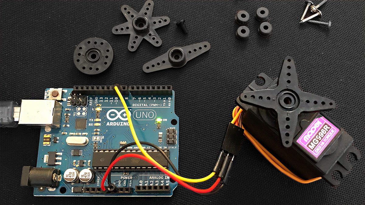
Controlling a servo with Arduino is relatively easy. If you pay attention to a few things, then you expand the flashing and squeaking Arduino world quickly with movements and kinetic interaction! This article explains the circuit and the code.
Servo: setup and connection
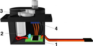
A servo consists of a motor control unit (1), an electric motor (2), a gearbox (3) and a potentiometer for position determination (4). All components are housed in a robust housing.
The servo motor is connected via a three-pole cable. These are two supply lines (plus and GND) and one data line.
Depending on the manufacturer, the cable colors may differ. Common combinations are brown-red-orange (GND, plus, data) or black-red-yellow (GND, plus, data). A look at the description of the servo motor is always appropriate to make sure that it is properly connected. An incorrect connection can lead to damage here.
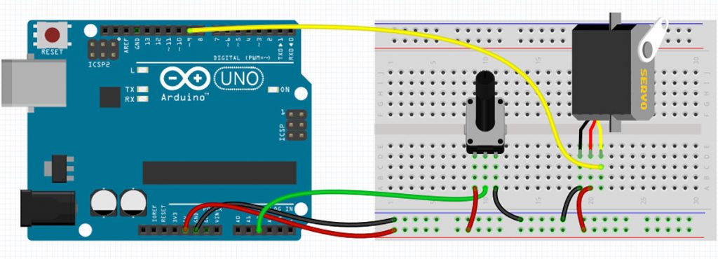
Circuit and sample program code
The example shows, a standard servomotor connected to the GND, 5V + and digital pin 9. Furthermore, a potentiometer is connected to the analog pin 2.
The program is the Knob example from the Arduino software (File> Examples> Servo> Knob).
#include <Servo.h>

Servo myservo;

int potpin = 0;
int val;

void setup() {
  myservo.attach(9);
}

void loop() {
  val = analogRead(potpin);
  val = map(val, 0, 1023, 0, 180);
  myservo.write(val);
  delay(15);
}
In this example, the servo motor is controlled to a position determined by the potentiometer at the analog pin 2. Of course, this is just an example to explain how it works. Importantly, the command myservo.write (val); sets the servomotor in a specific position between 0 and 180 degrees.
Control many servo motors with Arduino
A servo motor needs a lot of power for the movements. If you want to use more than one servo motor, I recommend using a servo shield like the Adafruit Robot Shield. It is a, on the Arduino attachable, extension of the Arduino.
The Adafruit Robot Servo can control up to 16 servomotors simultaneously. An external power supply is required for this. A pleasant side effect is that you do not occupy valuable channels of the Arduino for each servo motor. The shield is controlled by I2C. This is a digital data connection between the Arduino and the Servo Shield. It occupies only two! pins of the Arduion board.
To set up this communication, there is a library from Adafruit that can be integrated and used in no time at all.
As an alternative to the Adafruit Robot Servo Shield, there is a cheaper version of SunFounder.
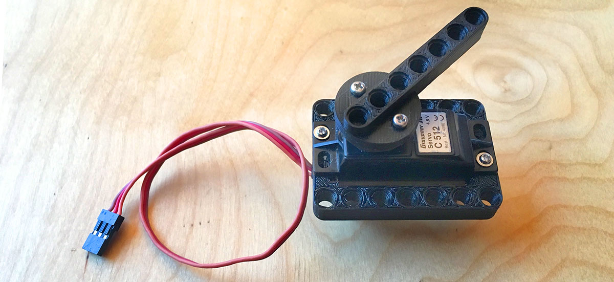
Tip: Unfortunately, normal servos do not fit LEGO technology. But with this little 3D model it works. Time for a 3D printer* 😉
Special form servo winch
It is a more powerful servomotor, which can rotate not only to 180 °, but depending on the type to 360 ° or 720 °. Winches are used in model making e.g. installed in sailing ships. Here you can view the product* on Amazon.
Expert knowledge: Control without library
To control the servomotor one uses a signal repeating every 20 milliseconds. It consists of a HIGH pulse, which is between 1 and 2 milliseconds long, and a LOW pulse. The duration of the HIGH pulse determines the target angle (normally from 0 to 180 °). In the Arduino software, the delayMicroseconds (x); use:
digital write (myServo, HIGH);
delay microseconds (1500);
digital write (myServo, LOW);
delay microseconds (18500);
Since the servo takes some time to adjust to the desired target angle, the signal must be repeated at least until the servo has reached the position.
Servo motors check their own adjustment angle with a built-in potentiometer. It happens here that a desired position can not be reached exactly. The servo will then self-correct, causing the servo to “shake”. To prevent this, the pulse should be switched to LOW after reaching the target angle.
As an alternative to the self-programmed signal, you can use the servo library. It comes with the Arduino software. The sweep example (File> Examples> Servo> Sweep) shows how to use a servo with the servo library.
// Sweep
// by BARRAGAN

#include Servo myservo;  	// creates a servo object

int pos = 0;

void setup(){
  myservo.attach(9);
}

void loop(){
  for(pos = 0; pos < 180; pos += 1) {
    myservo.write(pos);
    delay(15);
  }
  for(pos = 180; pos>=1; pos-=1) {
    myservo.write(pos);
    delay(15);
  }
}
Pingback: Let's build a Creepy Halloween candy dispenser with Arduino