This module of the RaylFX system controls the ambient lighting of the model railway. For this purpose, an RGBW LED strip is used as a light source.
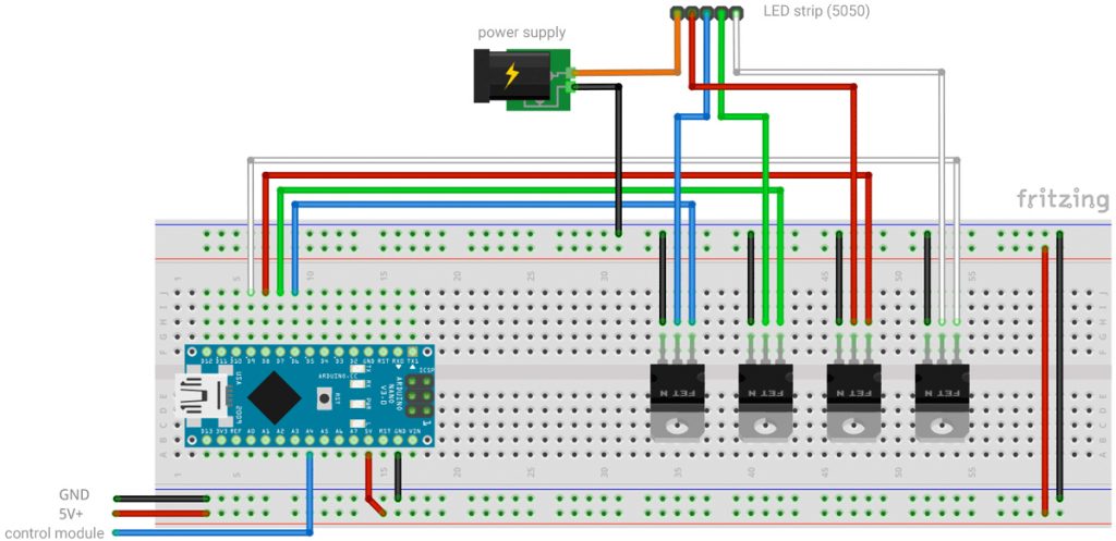
Wiring Diagram
The LED strip consists of four parallel circuits of LEDs (red, green, blue, white). In my strip, red, green and blue are combined in one LED housing, while the white LED is an extra component. All LEDs share the anode (positive pole). It is called common anode.
So when you buy it, you have to find a hint somewhere on the connection points of the LED segments, e.g. a +, a 5V+ or a 12V+.
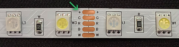
My LED strip had female pin headers as connectors, which were very easy to connect with patch cables.
As shown in the schematic, the GND of the external power supply must be connected to the GND of the Arduino board. The plus on the other hand must only be connected to the LED strip!
The LEDs are controlled by N-channel MOS-FET transistors. I use the IRF630N transistors for this. In contrast to normal transistors they don’t need any pre-resistors. The legs are called gate, drain and source. The source terminal is connected to GND. The drain terminal is connected to the respective LED color and is controlled by the gate. The gate is connected to the PWM pins of the Arduino nano board (D6 – blue, D9 – green, D10 – red, D11 – white).
Attention: The control signal of the RaylFX control module is applied to pin A4. It controls the time of day and is mandatory.
Components
- 1x Arduino Nano*
- 1x Breadboard and jumper wires*
- 1x RGBW-Set*
- 1x DC-Socked for screwing*
- 4x MOS-FET IRF630*
Code Settings
Four phases of the room lighting are passed through: sunrise, day, sunset, night. Several settings can be made in the code. These are explained in more detail in the code section. They are the light colors of the respective phases and the speed of the transition (frameSpeed).
int frameSpeed = 100;                    // Delay of the light transitions (the higher, the slower)
float lightColors[4][4] = {
  {200.0, 50.0, 0.0, 0.0},               // sunrise
  {0.0 , 0.0 , 0.0, 255.0},              // day
  {150.0, 0.0, 60.0, 50.0},              // sunset
  {0.0 , 0.0 , 60.0, 0.0}                // night
};
When uploading you have to make sure that the correct board is selected in the Arduino menu. To do this, “ATmega328P (Old Bootlaoder)” must also be selected in the Processor subitem of the Tools menu.
The following program code can be easily copied with the above mentioned changes and loaded onto the Arduino nano.
Code for the RaylFX Ambient Lighting Module
/*
    Rayl-FX Ambient Lighting Module
    StartHardware.org/en
*/

/* ***** ***** Settings ***** ***** ***** *****  ***** ***** ***** *****  ***** ***** ***** ***** */

int frameSpeed = 100;                    // Delay of the light transitions (the higher, the slower)
float lightColors[4][4] = {
  {200.0, 50.0, 0.0, 0.0},               // sunrise
  {0.0 , 0.0 , 0.0, 255.0},              // day
  {150.0, 0.0, 60.0, 50.0},              // sunset
  {0.0 , 0.0 , 60.0, 0.0}                // night
};

/* ***** ***** From here begins the program code, which does not need to be adjusted ***** ***** ***** ***** */

int bluePin = 6;                         // this pin connects to the blue channel of the RGBW-LEDs
int greenPin = 9;                        // this pin connects to the green channel of the RGBW-LEDs
int redPin = 10;                         // this pin connects to the red channel of the RGBW-LEDs
int whitePin = 11;                       // this pin connects to the white channel of the RGBW-LEDs

/* Variables for lightColors */
float currentColor[4];
float colorSteps[4][4];
int samples = 255;

int frameNumber = 0;
long frameTimer = 0;

boolean transitionDone = false;

int phase = 3;

/* Variables from the control module to determine the time of day */
boolean receive = false;
boolean receiveStarted = false;
int receiveTimeout = 10;
long receiveTimer = 0;
int receivedTime = 0;
int receivePulse = 0;
int lastReceivePulse = 0;
int receivePin = 18;
int myTime = 23;
int myOldTime = 0;

#define PAYLOAD_SIZE 2                    // mandatory for communication with master-module
int timeOfDay = 0;                        // stores timeOfDay of master-module (0 and 255)
byte nodePayload[PAYLOAD_SIZE];           // temporarily stores data of master-module

void setup() {
  Serial.begin(115200);                   // starts the serial communication
  pinMode(receivePin, INPUT);             // receiving pin from the control module

  for (int i = 0; i < 4; i++) {
    if (phase != 3) {
      if (lightColors[phase][i] < lightColors[phase + 1][i]) {
        colorSteps[phase][i] = (lightColors[phase + 1][i] - lightColors[phase][i]) / 255;
      } else if (lightColors[phase][i] > lightColors[phase + 1][i]) {
        colorSteps[phase][i] = (lightColors[phase][i] - lightColors[phase + 1][i]) / -255;
      }
    } else {
      if (lightColors[phase][i] < lightColors[0][i]) {
        colorSteps[phase][i] = (lightColors[0][i] - lightColors[phase][i]) / 255;
      } else if (lightColors[phase][i] > lightColors[0][i]) {
        colorSteps[phase][i] = (lightColors[phase][i] - lightColors[0][i]) / -255;
      }

    }
    Serial.println(colorSteps[phase][i]);
  }
}

void loop() {
  receiveFunction();                      // execute instructions for reception
  if (receiveStarted == false) {          // if no data is currently being received:

    if (myTime == 20) {                   // ***** sunset *****
      if (myOldTime != myTime) {          // when the hour switches
        phase = 1;                        // sets transition phase
        transitionDone = false;           // transition phase is executed
        Serial.println("sunset");
      }
    } else if (myTime == 6) {             // ***** sunrise *****
      if (myOldTime != myTime) {          // when the hour switches
        phase = 3;                        // sets transition phase
        transitionDone = false;           // Übergangsphase wird ausgeführt
        Serial.println("sunrise");
      }
    }
  }

  if ((frameTimer + frameSpeed < millis()) && (transitionDone == false)) {

    for (int i = 0; i < 4; i++) {
      if (phase != 3) {
        currentColor[i] = map(frameNumber, 0, 255, lightColors[phase][i], lightColors[phase + 1][i]);
      } else {
        currentColor[i] = map(frameNumber, 0, 255, lightColors[phase][i], lightColors[0][i]);
      }
    }

    frameNumber++;
    if (frameNumber > samples) {
      frameNumber = 0;
      if (phase == 3) {                       // automatic transition from sunrise to day
        phase = 0;
      } else if (phase == 1) {                // automatic transition from sunset to night
        phase = 2;
      } else {
        transitionDone = true;
      }
    }
    frameTimer = millis();
  }

  analogWrite(redPin, currentColor[0]);      // setting the LED color
  analogWrite(greenPin, currentColor[1]);    // setting the LED color
  analogWrite(bluePin, currentColor[2]);     // setting the LED color
  analogWrite(whitePin, currentColor[3]);    // setting the LED color

  myOldTime = myTime;
}

void receiveFunction() {                      // receives time of day from control-module
  receivePulse = digitalRead(receivePin);     // read out the receive pin

  if ((receiveTimer + receiveTimeout < millis()) && (receiveStarted == true)) {
    // on timeout and active reception
    receiveStarted = false;                   // end active reception
    myTime = receivedTime - 1;                // store received time
    receivedTime = 0;                         // reset the auxiliary variable for time reception
    Serial.println(myTime);                   // serial output
  }
  // if a pulse is detected at the receive pin that was not there before
  if ((receivePulse == 0) && (lastReceivePulse == 1)) {
    receiveTimer = millis();                  // restart timer
    if (receiveStarted == false) receiveStarted = true;  // start active reception, if not already done
    receivedTime++;                           // there was a pulse, so increase the auxiliary variable to receive time
  }
  lastReceivePulse = receivePulse;            // remember current state at pin for next pass
}