This module of the RaylFX system operates a traffic light system with two driving directions and pedestrian lights. In addition, there is street lighting and an optional night shutdown.
Wiring Diagram

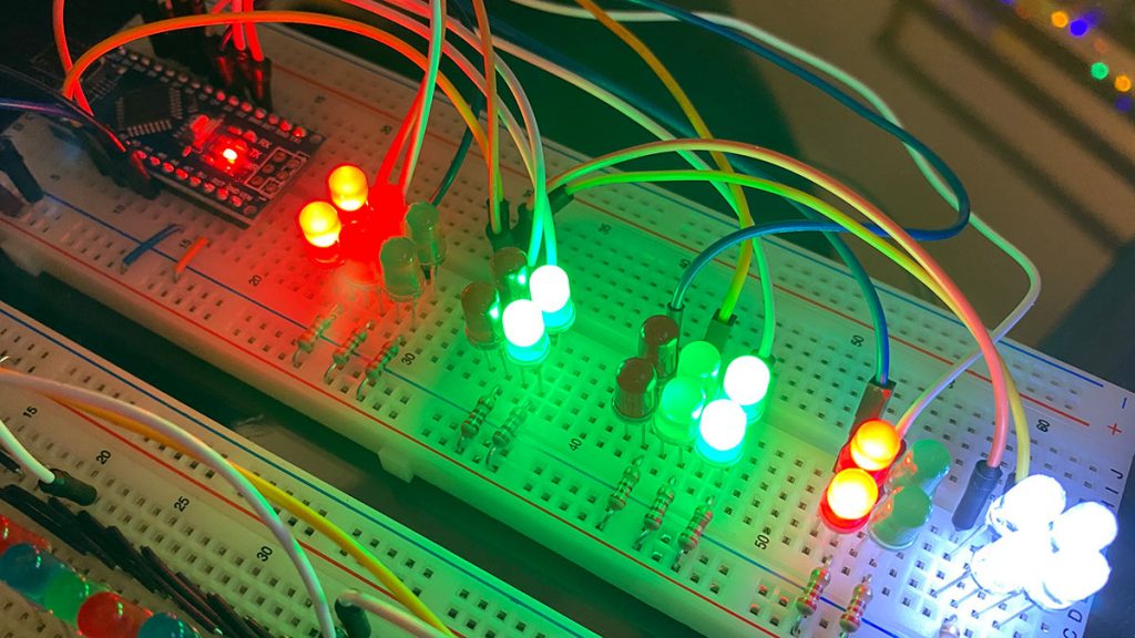
This module also works with an Arduino Nano. The LEDs for the traffic lights are connected to the digital channels 2 – 11. Each channel can supply up to 40mA. Since you need several single traffic lights for a traffic light system, you can extend the circuit by parallel connected LEDs. However, the brightness of the individual LEDs is reduced. At A2 and A3 the street lighting is operated. They are operated as digital outputs (D16, D17) and switch on controlled by the control module at night. The green cable on the left (SCL) is redundant – sorry.
Attention: The control signal of the RaylFX control module is applied to pin A4. It controls the time of day and is mandatory.
Code Settings
Several settings can be made in the code. The variable myAddress must be adapted to the system. This address may only occur once in the entire system (i.e. in all modules). The variable waitingTimes stores the duration of the individual color phases of the traffic light system. The variable nightShutdown can be set to true or false. If true, the traffic lights are switched off at night and flash yellow. With false this does not happen.
long waitingTimes[10] = {5000, 2000, 500, 2000, 500, 5000, 2000, 500, 2000, 500}; // waiting times of the traffic light phases
boolean nightShutdown = true;         // true = traffic light switches off at night (yellow flashing), false = traffic light does not switch off
When uploading you have to make sure that the correct board is selected in the Arduino menu. To do this, “ATmega328P (Old Bootlaoder)” must also be selected in the Processor subitem of the Tools menu.
The following program code can be easily copied with the above mentioned changes and loaded onto the Arduino nano.
Code for the RaylFX Traffic Light Module
/*
     Rayl-FX Traffic Light Module
     StartHardware.org/en
*/

/* ***** ***** Settings ***** ***** ***** *****  ***** ***** ***** *****  ***** ***** ***** ***** */

long waitingTimes[10] = {5000, 2000, 500, 2000, 500, 5000, 2000, 500, 2000, 500}; // waiting times of the traffic light phases
boolean nightShutdown = true;         // true = traffic light switches off at night (yellow flashing), false = traffic light does not switch off

/* ***** ***** From here begins the program code, which does not need to be adjusted ***** ***** ***** ***** */

int streetLampsPin1 = 16;              // this pin connects to the street lamps
int streetLampsPin2 = 17;              // this pin connects to more street lamps

int ledPins[10] = {2, 3, 4, 5, 6, 7, 8, 9, 10, 11};

int trafficLightPhases[12][10] = {
  {1, 0, 0, 0, 1, 0, 0, 1, 1, 0},  // state 0
  {1, 0, 0, 1, 0, 0, 0, 1, 1, 0},  // state 1
  {1, 0, 0, 1, 0, 0, 1, 0, 1, 0},  // state 2
  {1, 0, 0, 1, 0, 1, 0, 0, 1, 0},  // state 3
  {1, 1, 0, 1, 0, 1, 0, 0, 1, 0},  // state 4
  {0, 0, 1, 1, 0, 1, 0, 0, 0, 1},  // state 5
  {0, 0, 1, 1, 0, 1, 0, 0, 1, 0},  // state 6
  {0, 1, 0, 1, 0, 1, 0, 0, 1, 0},  // state 7
  {1, 0, 0, 1, 0, 1, 0, 0, 1, 0},  // state 8
  {1, 0, 0, 1, 0, 1, 1, 0, 1, 0},  // state 9
  {0, 1, 0, 0, 0, 0, 1, 0, 0, 0},  // state 10 // flash
  {0, 0, 0, 0, 0, 0, 0, 0, 0, 0}   // state 11 // flash
};

/* Memory Variables */
int streetLampsBrightness = 0;        // stores how bright the street lamps shine

/* Timer Variables */
long streetLampsTimer = 0;            // Timer of the street lamps
long trafficLightTimer = 0;
long trafficLightTimeout = 0;

/* State Variables */
int trafficLightState = 0;

String stateName;

/* */

/* Variables from the control module to determine the time */
boolean receive = false;
boolean receiveStarted = false;
int receiveTimeout = 10;
long receiveTimer = 0;
int receivedTime = 0;
int receivePulse = 0;
int lastReceivePulse = 0;
int receivePin = 18;
int myTime = 0;

#define PAYLOAD_SIZE 2                   // mandatory for communication with master-module
int timeOfDay  = 0;                         // stores timeOfDay of master-module (0 and 255)
byte nodePayload[PAYLOAD_SIZE];          // temporarily stores data of master-module

void setup() {
  Serial.begin(115200);                  // starts the serial communication
  pinMode(receivePin, INPUT);            // receiving pin from control-module
  for (int i = 0; i < 10; i++) {
    pinMode(ledPins[i], OUTPUT);
  }
  pinMode(streetLampsPin1, OUTPUT);
  pinMode(streetLampsPin2, OUTPUT);
  streetLampsOff();
}

void loop() {
  receiveFunction();                // execute instructions for reception
  if (receiveStarted == false) {    // If no data is currently being received:

    if (myTime > 22) {              // ***** late evening *****
      streetLampsOn();           // street lamps on
      showTrafficLightPhase();            // traffic light on

    } else if (myTime > 18) {       // ***** evening *****
      streetLampsOn();           // street lamps on
      showTrafficLightPhase();            // traffic light on

    } else if (myTime > 12) {       // ***** noon *****
      streetLampsOff();          // street lamps off
      showTrafficLightPhase();            // traffic light on

    } else if (myTime > 9) {        // ***** forenoon *****
      streetLampsOff();          // street lamps off
      showTrafficLightPhase();            // traffic light on

    } else if (myTime > 7) {        // ***** morning *****
      streetLampsOn();           // street lamps on
      showTrafficLightPhase();            // traffic light on

    } else {                        // ***** night *****
      streetLampsOn();           // street lamps on
      if (nightShutdown == true) {
        showTrafficLightOff();            // traffic light off
        trafficLightTimer = millis();      // resetting the traffic light timer for the next phase
        trafficLightState = 3;             // resetting the traffic light state
      } else {
        showTrafficLightPhase();          // traffic light on
      }
    }
  }
}

void streetLampsOn() {
  digitalWrite(streetLampsPin1, LOW);
  digitalWrite(streetLampsPin2, LOW);
}

void streetLampsOff() {
  digitalWrite(streetLampsPin1, HIGH);
  digitalWrite(streetLampsPin2, HIGH);
}

void showTrafficLightPhase() {
  if (trafficLightTimer + trafficLightTimeout < millis()) {
    trafficLightTimer = millis();
    trafficLightState++;
    if (trafficLightState >= 10) trafficLightState = 0;
    trafficLightTimeout = waitingTimes[trafficLightState];
    showTrafficLightPhase();
  }

  for (int i = 0; i < 10; i++) {
    if (trafficLightPhases[trafficLightState][i] == 1) {
      digitalWrite(ledPins[i], LOW);
    } else {
      digitalWrite(ledPins[i], HIGH);
    }
  }
}

void showTrafficLightOff() {
  // Flashing function for switched off traffic light
  if (millis() % 2000 > 1000) {
    for (int i = 0; i < 10; i++) {
      if (trafficLightPhases[11][i] == 1) {
        digitalWrite(ledPins[i], LOW);
      } else {
        digitalWrite(ledPins[i], HIGH);
      }
    }
  } else {
    for (int i = 0; i < 10; i++) {
      if (trafficLightPhases[10][i] == 1) {
        digitalWrite(ledPins[i], LOW);
      } else {
        digitalWrite(ledPins[i], HIGH);
      }
    }
  }
}

void receiveFunction() {                      // receives time of day from control-module
  receivePulse = digitalRead(receivePin);     // read out the receive pin

  if ((receiveTimer + receiveTimeout < millis()) && (receiveStarted == true)) {
    // on timeout and active reception
    receiveStarted = false;                   // end active reception
    myTime = receivedTime - 1;                // store received time
    receivedTime = 0;                         // reset the auxiliary variable for time reception
    Serial.println(myTime);                   // serial output
  }
  // if a pulse is detected at the receive pin that was not there before
  if ((receivePulse == 0) && (lastReceivePulse == 1)) {
    receiveTimer = millis();                  // restart timer
    if (receiveStarted == false) receiveStarted = true;  // start active reception, if not already done
    receivedTime++;                           // there was a pulse, so increase the auxiliary variable to receive time
  }
  lastReceivePulse = receivePulse;            // remember current state at pin for next pass
}