
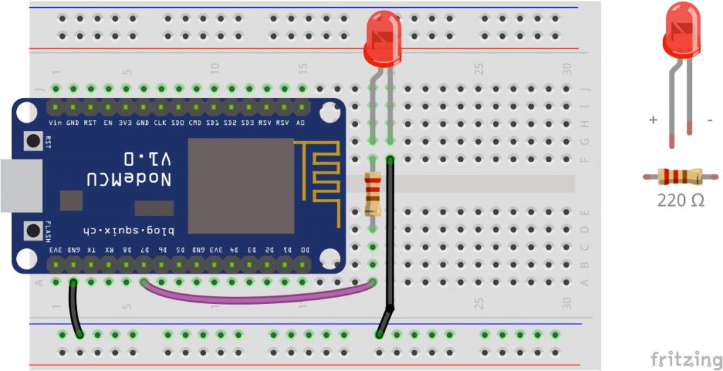
Now it it time to connect the NodeMCU to Wifi. We will use it as a server so we can connect it with the SmartPhone. The circuit stays the same, we will only change the code.
Circuit
Code to run the NodeMCU as a Server
The code is more complex. What happens is that the NodeMCU now acts as a webserver and is listening on the standard port 80. If you connect to its IP address it will show a webpage with a button. Press the button to switch the LED on and off.
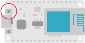
To make it run, fill in your Wifi name (SSID) and password, upload it to the NodeMCU and in the Arduino software open the Serial Monitor. You can find it at Tools>Serial Monitor. Set the baud rate (bottom of the Serial Monitor window) to 115200 and press the reset button on the NodeMCU.
The IP address is shown. Connect your smartphone to the same wifi and enter the IP in a browser window. The webpage will show a button to toggle the LED on the NodeMCU.
#include <ESP8266WiFi.h>
#include <ESP8266WebServer.h>

const char* ssid  = "XXXXXXXX";        // Wifi name (SSID)
const char* password = "XXXXXXXX";  // Wifi password

ESP8266WebServer server(80);    // Server port
String Temp = "";

int d7pin = D7;
int d7state = 0;

/* ***** ***** ***** ***** HTML ***** ***** ***** ***** */

const char HTML_header[] PROGMEM = R"=====(
<!DOCTYPE html>
<html>

<head>
    <meta content="text/html; charset=ISO-8859-1" http-equiv="content-type">
    <meta http-equiv="refresh" content="5">
    <title>WebSchalter</title>
</head>

<style>
    html {
        background-color: grey;
    }

    body {
        margin: auto;

        margin-top: 60px;
    }

    button {
        height: 120px;
        width: 100%;
        font-size: 48px;
        background-color: cornflowerblue;
        border: none;
        color: white;
        margin-bottom: 10px;
    }

    button:active {
        background-color: darkturquoise;
        color: white;
        border: none;
    }

    button.on{
        background-color: red;
    }

    a {
        text-decoration: none;
    }


</style>

<body>)=====";

String HTML_d7_off = "<a href=\"/args?d7pin=1\"><button>d7 - LED</button></a>";
String HTML_d7_on = "<a href=\"/args?d7pin=0\"><button class=\"on\">d7 - LED</button></a>";

const char HTML_footer[] PROGMEM = R"=====(
</body>
</html>
)=====";

/* ***** ***** ***** ***** Setup ***** ***** ***** ***** */
void setup()
{
  pinMode(d7pin , OUTPUT);                  // D7 set as Output
  Serial.begin(115200);                     // start serial communication
  connectToWifi();                          // start wifi
}

/* ***** Webpage: executed when "http://<ip address>/" is called ***** */

void the_webpage() {
  Temp = HTML_header;                        // top part of the html

  if (d7state == 1) {                        // d7 part of html page – the html code for a button
    Temp += HTML_d7_on;
  } else {
    Temp += HTML_d7_off;
  }

  Temp += HTML_footer;                       // bottom part of the html page
  server.send(200, "text/html", Temp);       // serving the html page
}

/* ***** ***** ***** ***** Event Functions ***** ***** ***** ***** */

void handleArgs() {
  if (server.arg("d7pin")!= ""){             // if specific argument is not empty
    d7state = server.arg("d7pin").toInt();   // set d7 pin to received argument
  }

  the_webpage();                             // deliver webpage
}

/* ***** ***** ***** Wifi Functions ***** ***** ***** */

void showStates(){                           // map all states to pins
  digitalWrite(d7pin, d7state);
}

/* ***** ***** ***** ***** Loop ***** ***** ***** ***** */

void loop() {
  server.handleClient();                     // update function for server
  showStates();                              // map states to pins
  delay(10);                                 // some time to process
}

/* ***** ***** ***** Wifi Functions ***** ***** ***** */

void connectToWifi() {
  Serial.println();
  Serial.print("Connect to"); Serial.println(ssid);
  WiFi.begin(ssid, password);

  while (WiFi.status() != WL_CONNECTED) {
    delay(500);
    Serial.print(".");
  }

  Serial.println("");
  Serial.println("Wifi connected");
  Serial.println ("Webserver running, waiting for ESP8266 ...");

  delay(2000);
  Serial.println();
  Serial.println("IP addresse of the web server is: ");
  Serial.println(WiFi.localIP());   // output the ip
  server.on("/", the_webpage);      // show website on root call
  server.on("/args", handleArgs);   // associate the handler function to the path

  server.begin();                   // start the server
  Serial.println ("Webserver running, waiting for ESP8266 ...");
}
The Complete Tutorial
- Interactive Christmas Decoration – Part 1: Preparation
- Interactive Christmas Decoration – Part 2: Make it blink
- Interactive Christmas Decoration – Part 3: Server and LED
- Interactive Christmas Decoration – Part 4: Server, LED, RGB
- Interactive Christmas Decoration – Part 5: Analog Input with LDR
Dieser Beitrag ist auch auf Deutsch verfügbar: Workshop: Interaktive Weihnachtsdekoration Teil 3 – Server und LED
Pingback: Interactive Christmas Decoration – Part 4: Server, LED, RGB - StartHardware - Tutorials for Arduino
Pingback: Interactive Christmas Decoration – Part 2 - StartHardware - Tutorials for Arduino
Pingback: Workshop: Interaktive Weihnachtsdekoration Teil 3 – Server und LED – Arduino Tutorial
Pingback: Interactive Christmas Decoration – Part 5: Analog Input with LDR - StartHardware - Tutorials for Arduino